Searching for Savings Potential
With over two decades of experience in plant systems optimization, we are expert at identifying and extracting the unused potential in your equipment through the optimization of existing processes resulting in reduced downtime, energy use and financial savings. So where do we look to unlock your potential?
One area is the reduction of false air entrainment. Design modifications or a targeted selection of materials can reduce energy requirements and/or increase the service life of components thus keeping plants online longer.
Thermal processes in particular, such as calcination in rotary kilns or thermal waste gas aftertreatment, require a high degree of process understanding for optimization – of the interaction and detailed functioning of individual apparatuses. Questions often arise that cannot be solved on the basis of data sheets alone – such as flow profiles or precise temperature distributions. When it comes to complex and often difficult-to-access equipment, taking measurements is equally arduous. This is where computer-aided simulations can help.
Computer-aided process analysis – Computational Fluid Dynamics
Based on known or easily measurable boundary conditions, a CFD (Computational Fluid Dynamics) simulation can be used to build up a comprehensive, detailed understanding of the process and map the activity computationally. After model generation and validation of the actual apparatus state, various influencing parameters and their effect can then be quickly and reliably checked or predicted by varying the model, as is well illustrated in the following example: a simple and quick solution with the aid of computer-aided process analysis.
Combustion Chamber Exhaust Gases Thermal Aftertreatment Flow Simulation
We assisted a customer regarding problems they experienced commissioning a newly built plant for thermal post-combustion of exhaust gases from a test rotary kiln: During regular operation, there was a significant increase in energy consumption and waste gas volume flow. The ability to control adjacent plant components was also affected.
To find a solution, we first collected measurement data and examined the problem using an energy balance calculation. In this way, we were able to uncover a strong false air intake, which explained the increased energy demand and the high exhaust gas volume. We were able to identify a fresh air flap as the only possible source of false air: It supplied cooling air to protect downstream plant components – imperative for the operation. So how could this function be maintained but the false air be eliminated?
The air required for exhaust gas cooling during normal operation is drawn in independently by the negative pressure in the combustion chamber. However, the geometrical arrangement of the cooling air inlet and combustion chamber outlet resulted in back-mixing of the fresh air in the direction of the combustion chamber, and the energy required to achieve the required combustion chamber temperature was significantly increased.
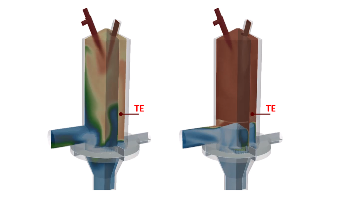
In order to verify this hypothesis, we carried out a fluid dynamic calculation (CFD) – the basis was the known apparatus geometry with the collected boundary data. The results are shown graphically in the figure (temperature distribution in the flue gas: blue = cold, red = hot). On the left the condition before our optimization: A clear entry of cold air from the fresh air flap up to the control thermocouple (TE). Thus, the established thesis could be confirmed in the simulation.
With the problem now precisely defined, we were able to work out a solution – as cost-effectively as possible with very little construction effort. Here, we again made use of simulation: proposals could be directly checked virtually.
In the end, the simplest and quickest option was to install a baffle plate that prevents the cold fresh air from mixing back with the flue gas in the combustion chamber. The figure on the right shows the results in the CFD simulation graphically – a uniformly high temperature in the combustion chamber.
Figure 1: Gas temperature distribution in the combustion chamber before (left) and after (right) the installation of the baffle
Computer-aided simulation based on easily accessible data was able to effectively identify the problem and made the development of proposed solutions simple and fast: in a short time and with little financial effort, the process was analyzed and a solution for optimization was developed.
Flow Simulations in Other Areas
Using a similar approach, we can also identify the formation of hotspots or areas with high exhaust gas velocities that lead to increased material stress and make equipment failure more likely. Early detection reduces failures. Here, too, simulations can then be used to suggest solutions – to specifically increase plant availability, for example by selecting different materials or making changes to process controls.
Both approaches can help to reduce costs: by lowering energy consumption or reducing plant downtime, maintenance and repair costs. IBU-tec has been advising customers on optimized management of their thermal processes and plants for years. With our expertise and many years of experience, we have already been able to solve customer problems in a large number of projects.
If you still suspect potential in your process management or know of areas that are not running optimally, please contact our colleagues from plant optimization!


